loadSync support
Find answers to your questions on how to utilize loadSync
loadSync
The loadSync device reads a sync signal from an external source, like another measuring system, and leaves a time marker in the loadsol recording. This time marker allows to synchronize the recorded data of the external system with those of the loadsol system.
Connect the hardware
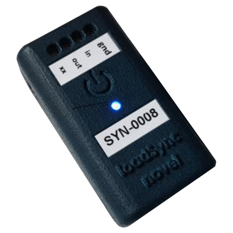
The loadSync device has a port with 4 screws, which can be used to connect wires for:
- gnd – ground
- in – sync-in
- out – sync-out (in beta, not usable yet)
- xx – (not connected)
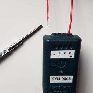
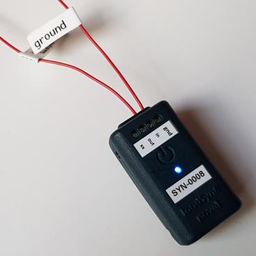
To connect a wire, coming from an external source, open the screw a bit, insert the stripped end of the wire into the hole in the front of the device, and tighten the screw carefully.
To bring an external sync signal to the loadsol system, two wires need to be connected: One to the ground and one to the sync-in port.
The external sync signal needs to be a TTL signal. (High level indicates sync event and should be within the range from 3 V to 5 V). The duration between successive sync signals should be 200 ms or more.
The loadSync device has an internal rechargeable battery and an internal memory (OBM – onboard memory), comparable to the battery and memory of the loadsol II electronics. Also, the status LED and the reset button work like they do in the loadsol electronics. Please refer to the corresponding chapter in this manual.
The housing has a clip on the lower side which can be used for fixing the device on shoe laces, for instance.
Usage in loadapp
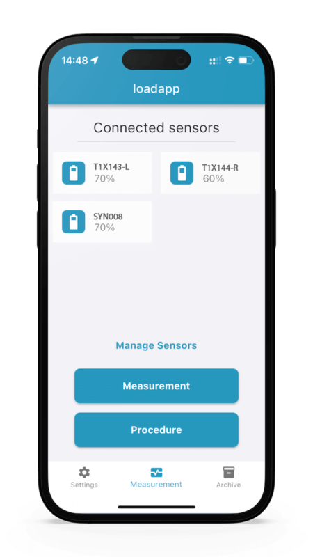
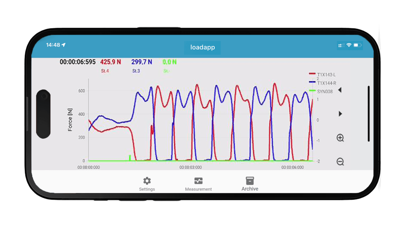
The loadSync device is used in the loadapp like a loadsol insole. As it is connected by wires to the external system, it should stay close to this external system. If the app is used in the “Stream” recording mode, make sure that the loadSync device stays in the Bluetooth receiving range of the smartphone. – If the “OBM” recording mode is used, data will be stored on the internal memory of the loadSync device, so it does not matter whether it leaves the Bluetooth range of the phone or not.
Interpretation
From the value of the loadSync signal, you can observe the time delay between the arrival of the sync-in signal and the next incoming loadsol frame.
The signal has a resolution of 1 ms (millisecond) and indicates:
- 0 N: No sync signal is received
- 10 N: Sync signal arrived at the same moment as the loadsol frame was measured
- 20 N: Sync signal arrived 1 ms before the loadsol frame was measured
- 30 N: Sync signal arrived 2 ms before the loadsol frame was measured
- (continues similarly)
- 90 N: Sync signal arrived 8 ms before the loadsol frame was measured
- 100 N: Sync signal arrived 9 ms before the loadsol frame was measured
Therefore, the sync values will range between 10 and 50 N for 200 Hz recordings (with a frame duration of 5 ms) and between 10 and 100 N for 100 Hz recordings (with a frame duration of 10 ms).
The following example was recorded with a 200 Hz scanning rate, and an external sync signal with 1 sync pulse per second:

If the insole’s force curves are dimmed and the force axis is zoomed, the peaks of the sync signal become more visible:

The 4 sync peaks are reading: 30 – 50 – 30 – 50 N, which means that they arrived 2 – 4 – 2 – 4 ms before the frame was measured, as shown in the app when the cursor is placed on the peak.

